- Home
- Cable Glands
- Products
- Unions
- PX780REX | RapidEx Barrier Union
- Ex ta
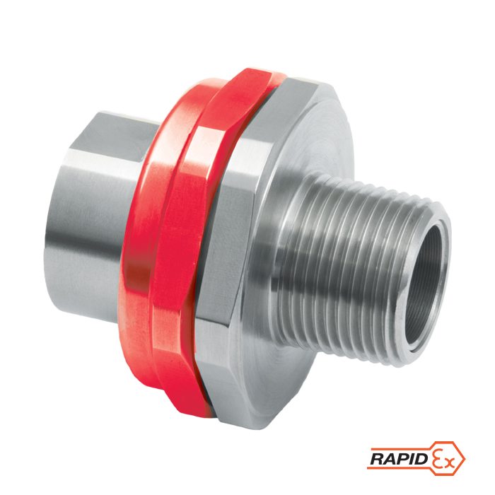
PX780REX | RapidEx Barrier Union Available in brass, nickel plated brass, aluminium & stainless Steel
We'd like to keep in touch
We have some exciting things in the pipeline - if you'd like to be the first to know please enter your email address below.
In-Line Union, Globally Approved, Explosive Atmosphere Barrier Cable / Conduit Accessory
- RapidEx liquid pour sealing system
• Enhances reliability, reduces risk
• Reduces man hours
• Reduces cost - Allows the connection of conduit or glands to equipment
- Suitable for rigid or flexible conduit
- Integral coupling eliminates the need to rotate the conduit
- General Purpose / industrial version available
- Equipment interface ‘O’ ring seal available
- -60°C to +85°C
- Globally marked, IECEx, ATEX & cCSAus
Note: Male-to-Male or Female-to-Female thread option available.
Available with an equipment interface ‘O’ ring seal. For such options please add the suffix letter “R” after the type number in the ordering reference above, e.g. PX780REXRDM2M2.
For epoxy compound version please remove “REX” from ordering reference.
If 2 separate enclosures are required to be connected together please contact CMP Products
Patent granted: ES2287986, NO 2287986, TR 2287986, AU 2010284848, AU 2014274614, GB 2485114, SG 178839, US 8872027, US 9484133, US 9774178
| Design Specification | BS 6121:Part 1:1989, IEC 62444, EN 62444 |
| Enclosure Protection | IK10 to IEC 62262 (20 joules) Brass & Stainless Steel only |
| ATEX Certificate | CML 18ATEX1327X |
| UKEX Certificate | CML 21UKEX1240X |
| Code of Protection | II 2G 1D Ex db IIC Gb, Ex eb IIC Gb, Ex ta IIIC Da IM2 Ex db I Mb / Ex eb I Mb |
| Compliance Standards | EN 60079-0,1,7,31 |
| IECEx Certificate | IECEx CML 18.0190X |
| Code of Protection | Ex db IIC Gb, Ex eb IIC Gb, Ex ta IIIC Da IP6X, Ex db I Mb, Ex eb I Mb |
| Compliance Standards | IEC 60079-0,1,7,31 |
| cCSAus Certificate | 1055233 |
| Code of Protection | Class I, Div 1 & 2, Groups A,B,C,D ; Enclosure type 4X : Class I, Zone 1, AEx de II ; Ex de II |
| Compliance Standards | C22.2 No.0,0.5,30,94, CAN/CSA E60079-0,1,7, CAN/CSA E61241-1, UL Std 50, 1203, UL 60079-0,1,7 |
| EAC Certificate (Formerly GOST R, K & B) | C-GB.A07.B.04602/22 |
| INMETRO Approval | TÜV 12.1334U |
| CCC Certificate | 2020322313003177 |
| UkrSEPRO | CU 19.0371X |
| CCOE / PESO (India) Certificate | Ex d: P548696, Ex e: P533772 |
| Marine Approvals | LRS: 01/00173 |
| Ingress Protection Rating ** | IP66 when fitted with a CMP ‘O’ ring or Entry Thread Seal** |
| Available Materials | Brass (standard), Electroless Nickel Plated Brass, Aluminium, Stainless Steel |
| ECAS Certificate | 24-03-106290/E24-03-110155/NB0007 |
| SANS | MS-XPL21962 21.0303X |
** When CMP installation accessories are used. Refer to Maintaining a Seal for further information.
Certificates
Product Selection Table
Click here to view how to order
| METRIC | NPT | ||||||||||||
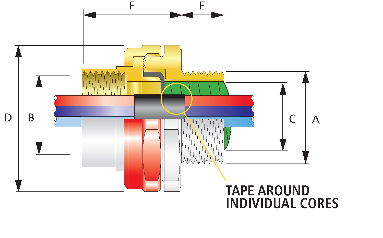
| Ordering Reference (Brass, Metric) | Male Forward Thread Size 'A' | Minimum Thread Length 'E' | Female Rear Thread Size 'B' | Ordering Reference (Brass, NPT) | Male Forward NPT Thread Size 'A' | Minimum NPT Thread Length 'E' (in) | Female Rear Thread Size 'B' | Diameter Over Cores 'C' | Max. Number of Cores | Protrusion Length 'F' | Across Flats Hex 'D' | Across Corners Ø 'D' | Installation Torque (Nm) |
| PX780REXDM2M2 | M20 X 1.5 | 0.59 | M20 X 1.5 | PX780REXDT1T1 | ½" | 0.79 | ½" | 0.50 | 21 | 1.42 | 1.81 | 1.99 | 7 |
| PX780REXDM3M3 | M25 X 1.5 | 0.59 | M25 X 1.5 | PX780REXDT2T2 | ¾" | 0.80 | ¾" | 0.69 | 30 | 1.42 | 1.97 | 2.17 | 10 |
| PX780REXDM4M4 | M32 X 1.5 | 0.59 | M32 X 1.5 | PX780REXDT3T3 | 1" | 0.98 | 1" | 0.93 | 50 | 1.42 | 2.36 | 2.60 | 15 |
| PX780REXDM5M5 | M40 X 1.5 | 0.59 | M40 X 1.5 | PX780REXDT4T4 | 1¼" | 1.01 | 1¼" | 1.18 | 59 | 1.42 | 2.56 | 2.81 | 25 |
| PX780REXDM6M6 | M50 X 1.5 | 0.59 | M50 X 1.5 | PX780REXDT5T5 | 1½" | 1.03 | 1½" | 1.61 | 115 | 1.42 | 2.95 | 3.25 | 30 |
| PX780REXDM7M7 | M63 X 1.5 | 0.59 | M63 X 1.5 | PX780REXDT6T6 | 2" | 1.06 | 2" | 2.11 | 115 | 1.42 | 3.55 | 3.91 | 45 |
| PX780REXDM8M8 | M75 X 1.5 | 0.59 | M75 X 1.5 | PX780REXDT7T7 | 2½" | 1.57 | 2½" | 2.53 | 140 | 1.54 | 3.91 | 4.30 | 45 |
| PX780REXDM9M9 | M90 X 2.0 | 0.94 | M90 X 2.0 | PX780REXDT8T8 | 3" | 1.63 | 3" | 2.96 | 140 | 1.65 | 4.72 | 5.20 | 45 |
| PX780REXDM10M10 | M100 X 2.0 | 0.94 | M100 X 2.0 | - | - | - | - | 3.31 | 200 | 3.70 | 5.71 | 6.28 | 45 |
| Dimensions displayed in inches unless otherwise stated | |||||||||||||
| METRIC | NPT | ||||||||||||
| Ordering Reference (Brass, Metric) | Male Forward Thread Size 'A' | Minimum Thread Length 'E' | Female Rear Thread Size 'B' | Ordering Reference (Brass, NPT) | Male Forward NPT Thread Size 'A' | Minimum NPT Thread Length 'E' (in) | Female Rear Thread Size 'B' | Diameter Over Cores 'C' | Max. Number of Cores | Protrusion Length 'F' | Across Flats Hex 'D' | Across Corners Ø 'D' | Installation Torque (Nm) |
| PX780REXDM2M2 | M20 X 1.5 | 15.0 | M20 X 1.5 | PX780REXDT1T1 | ½" | 0.79 | ½" | 12.6 | 21 | 36.0 | 46.0 | 50.6 | 7 |
| PX780REXDM3M3 | M25 X 1.5 | 15.0 | M25 X 1.5 | PX780REXDT2T2 | ¾" | 0.80 | ¾" | 17.5 | 30 | 36.0 | 50.0 | 55.0 | 10 |
| PX780REXDM4M4 | M32 X 1.5 | 15.0 | M32 X 1.5 | PX780REXDT3T3 | 1" | 0.98 | 1" | 23.6 | 50 | 36.0 | 60.0 | 66.0 | 15 |
| PX780REXDM5M5 | M40 X 1.5 | 15.0 | M40 X 1.5 | PX780REXDT4T4 | 1¼" | 1.01 | 1¼" | 30.0 | 59 | 36.0 | 65.0 | 71.5 | 25 |
| PX780REXDM6M6 | M50 X 1.5 | 15.0 | M50 X 1.5 | PX780REXDT5T5 | 1½" | 1.03 | 1½" | 41.0 | 89 | 36.0 | 75.0 | 82.5 | 30 |
| PX780REXDM7M7 | M63 X 1.5 | 15.0 | M63 X 1.5 | PX780REXDT6T6 | 2" | 1.06 | 2" | 53.7 | 115 | 36.0 | 90.2 | 99.2 | 45 |
| PX780REXDM8M8 | M75 X 1.5 | 15.0 | M75 X 1.5 | PX780REXDT7T7 | 2½" | 1.57 | 2½" | 64.3 | 140 | 39.0 | 99.3 | 109.2 | 45 |
| PX780REXDM9M9 | M90 X 2.0 | 24.0 | M90 X 2.0 | PX780REXDT8T8 | 3" | 1.63 | 3" | 75.3 | 140 | 42.0 | 120.0 | 132.0 | 45 |
| PX780REXDM10M10 | M100 X 2.0 | 24.0 | M100 X 2.0 | - | - | - | - | 84.0 | 200 | 94.0 | 145.0 | 159.5 | 45 |
| Dimensions displayed in millimeters unless otherwise stated | |||||||||||||
IEC 60079-1 – Flameproof Path Properties
A flameproof joint or flame path is defined by IEC 60079-1 as a “place where the corresponding surfaces of two parts of an enclosure, or the conjunction of enclosures, come together and which prevents the transmission of an internal explosion to the explosive gas atmosphere surrounding the enclosure”.
Read moreCable Gland for Cables Entering Ex d & Ex n Equipment
The following page identifies and illustrates the minimum requirements for flameproof type ‘d’ (Ex d) and type of enclosure protection ‘n’ (Ex n) cable glands.
Read moreCable Deformation with Temperature Change
Another factor to consider is that when cables are installed in connection with offshore electrical equipment, the temperature passing through the cable when the circuits have been energised can quite easily reach +70°C and above over prolonged periods.
Read moreVisit our Knowledge Base for technical expertise and advice, gathered over CMP's 60+ years' experience in the art of terminating cable glands.
Sign up now


