- Home
- Cable Glands
- Products
- Explosive Atmosphere
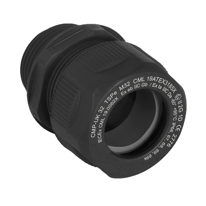
- TSPe Ex | Ex eb, Ex ta | Strain Relief Plastic Cable Gland
- Ex ta
| Colour | Suffix | Metric Ordering Example | NPT Ordering Example | |
| Black - RAL9011 | - | 12TSPE1TA | 12TSPE1TAT | |
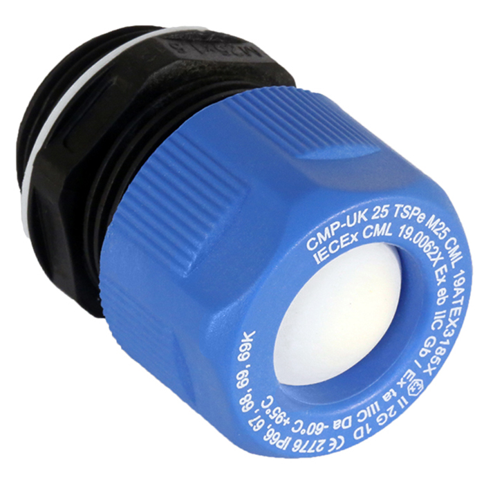
| Blue - RAL5015 | 4 | 12TSPE1TA4 | 12TSPE1TA4T | |
-
IP66, 67, 68, 69K
-
+95°C to -40°C
TSPe Ex | Ex eb, Ex ta | Strain Relief Plastic Cable Gland For all types of Unarmoured & Braided / Screened Cables
We'd like to keep in touch
We have some exciting things in the pipeline - if you'd like to be the first to know please enter your email address below.
The TSPe Ex polymer strain relief range of cable glands are suitable for use in explosive atmospheres with unarmoured or braided cable when terminated inside the enclosure, and have a temperature rating of +95°c to -60°c.
With the widest cable sealing range on the market, the TSPe Ex reduces the number of different sized cable glands required for projects, reducing the overall cost.
The TSPe Ex range meets the requirements of well-known cable gland standards including EN 62444 and IEC 62444.
For more specific applications IP68 & IP69X ingress discs or plugs are available.
Features include:
- Halogen and phosphorus-free
- Finger-locking seal provides superior cable retention and strain relief
- Approved to the latest editions of IEC/EN 60079
- Internationally marked IECEx & ATEX
- Intrinsically safe (Ex i) blue nut version available
- 3rd party certified to IEC/EN62444
- Widest cable range take for any comparable cable gland
- Low weight with high stiffness and strength
- Anti-vibration technology prevents gland loosening in operation
- Transit disc or IP68, IP69 and IP69K rated IP plug options available
- Approved entry thread sealing washer included
- For clearance holes the TSPe must be installed using a CMP metallic locknut
(available with the cable gland using ordering suffix 2TN)
Tightening tools may be required to aid installation. For further information, please click here.
| Design Specification | IEC 62444, EN 62444 (EN Metric only) |
| Mechanical Classifications* | 12-16 Impact = Level 5, 20-63 Impact = Level 6, Cable Anchorage = Type A |
| Enclosure Protection | 12-16 IK07 to IEC 62262 (4 joules), 20-63 IK08 to IEC 62262 (7 joules) |
| Ingress Protection Rating** | IP66, IP67, IP68**, IP69 & IP69K |
| Cable Gland Material | Halogen-free Polyamide |
| Seal Material | CMP SOLO LSF Halogen-free Thermoset Elastomer |
| Cable Type | Unarmoured & Braided when terminated inside enclosure |
| Sealing Technique | CMP Unique finger-locking type seal |
| Sealing Area(s) | Cable Outer Sheath |
| ATEX Certificate | CML 19ATEX3185X |
| Compliance Standards | EN 60079-0,7,31 |
| Code of Protection | II 2G 1D, Ex eb IIC Gb, Ex ta IIIC Da |
| IECEx Certificate | IECEx CML 19.0062X |
| Compliance Standards | IEC 60079-0,7,31 |
| Code of Protection | Ex eb IIC Gb, Ex ta IIIC Da |
| EAC Certificate | RU C-GB. AД07.B.02516/20 |
| SANS | IA S-XPL21804 21.0014X |
| Marine Approvals | TAE000000Y |
| CCC Certificate | 2020322313003450 |
| CCOE / PESO (India) Certificate | Ex e: P533772 |
| ECAS Certificate | 24-03-106290/E24-03-110155/NB0007 |
* Mechanical classifications applied as per IEC/EN 62444
** IP68 tested to 300 kPa for 16 hours (equivalent to 30 metres water depth)
Certificates


Click here to view how to order
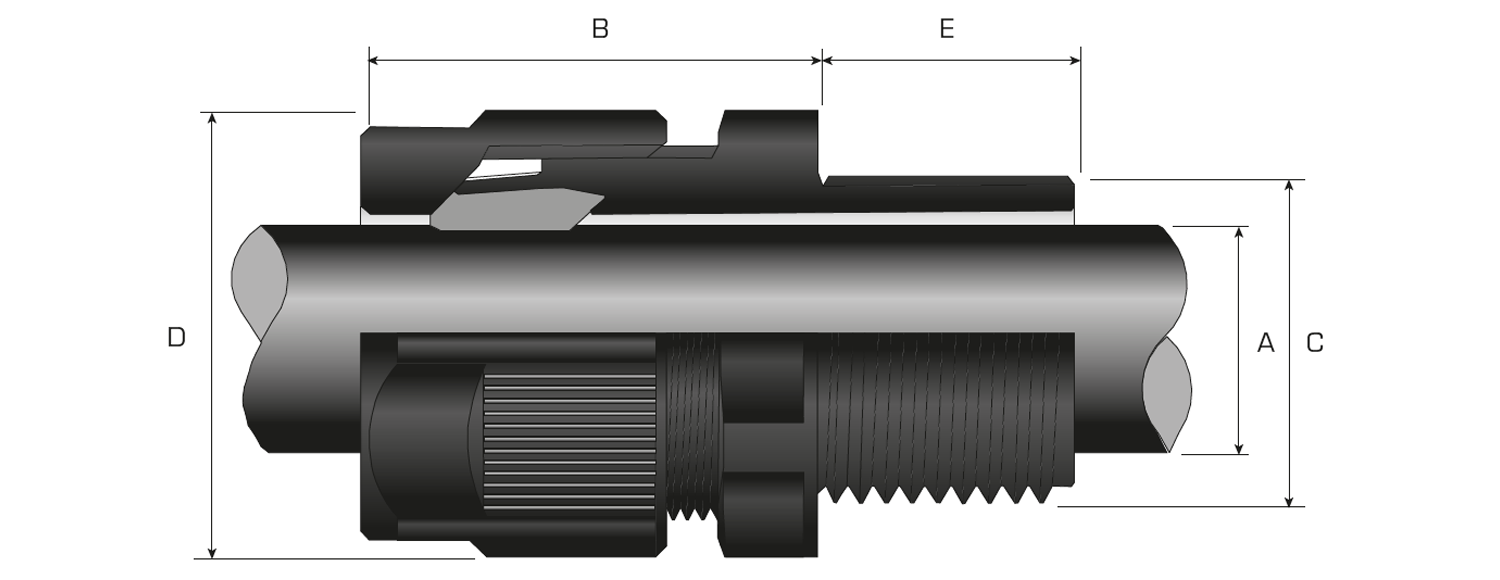
| Dual Seal | Available Entry Threads 'C' | Overall Cable Diameter 'A' | Across Flats 'D' | Across Corners 'D' | Protrusion Length 'B' | ||||||
| Standard | Option | ||||||||||
| Cable Gland Only | Cable Gland with Locknut | Metric | Thread Length (Metric) 'E' | Long Thread Length (Metric) 'E' | NPT | Thread Length (NPT) 'E' | Min | Max | Max | Max | |
| 16DTSPe1TA | 16DTSPe2TN | M16 | 9.0 | 15.0 | 3⁄8” | 11.0 | 3.2 | 10.0 | 19.0 | 20.9 | 27.0 |
| 20DTSPe1TA | 20DTSPe2TN | M20 | 10.0 | 15.0 | 1⁄2” | 14.0 | 5.5 | 14.0 | 24.0 | 26.2 | 30.5 |
| 25DTSPe1TA | 25DTSPe2TN | M25 | 10.0 | 15.0 | 3⁄4” | 15.0 | 9.0 | 18.0 | 30.0 | 32.7 | 36.0 |
| 32DTSPe1TA | 32DTSPe2TN | M32 | 12.0 | 15.0 | 1” | 18.0 | 12.5 | 25.0 | 40.0 | 43.6 | 41.0 |
| 40DTSPe1TA | 40DTSPe2TN | M40 | 12.0 | 18.0 | 1 1⁄4” | 18.0 | 19.0 | 32.0 | 50.0 | 54.5 | 49.0 |
| 50DTSPe1TA | 50DTSPe2TN | M50 | 12.0 | 18.0 | 1 1⁄2” | 19.0 | 22.0 | 38.0 | 58.0 | 63.2 | 59.0 |
| 63DTSPe1TA | 63DTSPe2TN | M63 | 15.0 | 18.0 | 2” | 20.0 | 28.0 | 48.0 | 68.0 | 74.1 | 64.0 |
| Standard Seal | Available Entry Threads 'C' | Overall Cable Diameter 'A' | Across Flats 'D' | Across Corners 'D' | Protrusion Length 'B' | ||||||
| Standard | Option | ||||||||||
| Cable Gland Only | Cable Gland with Locknut | Metric | Thread Length (Metric) 'E' | Long Thread Length (Metric) 'E' | NPT | Thread Length (NPT) 'E' | Min | Max | Max | Max | |
| 12TSPe1TA | 12TSPe2TN | M12 | 9.0 | 15.0 | 1⁄4” | 11.0 | 3.0 | 6.5 | 15.0 | 16.4 | 27.0 |
| 16STSPe1TA | 16STSPe2TN | M16 | 9.0 | 15.0 | 3⁄8” | 11.0 | 3.0 | 7.0 | 19.0 | 20.9 | 27.0 |
| 16TSPe1TA | 16TSPe2TN | M16 | 9.0 | 15.0 | 3⁄8” | 11.0 | 6.0 | 10.0 | 19.0 | 20.9 | 27.0 |
| 20STSPe1TA | 20STSPe2TN | M20 | 10.0 | 15.0 | 1⁄2” | 14.0 | 5.0 | 10.0 | 24.0 | 26.2 | 30.5 |
| 20TSPe1TA | 20TSPe2TN | M20 | 10.0 | 15.0 | 1⁄2” | 14.0 | 9.0 | 14.0 | 24.0 | 26.2 | 30.5 |
| 25STSPe1TA | 25STSPe2TN | M25 | 10.0 | 15.0 | 3⁄4” | 15.0 | 9.0 | 15.5 | 30.0 | 32.7 | 36.0 |
| 25TSPe1TA | 25TSPe2TN | M25 | 10.0 | 15.0 | 3⁄4” | 15.0 | 12.5 | 18.0 | 30.0 | 32.7 | 36.0 |
| 32STSPe1TA | 32STSPe2TN | M32 | 12.0 | 15.0 | 1” | 18.0 | 12.5 | 19.0 | 40.0 | 43.6 | 41.0 |
| 32TSPe1TA | 32TSPe2TN | M32 | 12.0 | 15.0 | 1” | 18.0 | 17.0 | 25.0 | 40.0 | 43.6 | 41.0 |
| 40STSPe1TA | 40STSPe2TN | M40 | 12.0 | 18.0 | 1 1⁄4” | 18.0 | 19.0 | 27.0 | 50.0 | 54.5 | 49.0 |
| 40TSPe1TA | 40TSPe2TN | M40 | 12.0 | 18.0 | 1 1⁄4” | 18.0 | 24.0 | 32.0 | 50.0 | 54.5 | 49.0 |
| 50STSPe1TA | 50STSPe2TN | M50 | 12.0 | 18.0 | 1 1⁄2” | 19.0 | 22.0 | 32.0 | 58.0 | 63.2 | 59.0 |
| 50TSPe1TA | 50TSPe2TN | M50 | 12.0 | 18.0 | 1 1⁄2” | 19.0 | 28.0 | 38.0 | 58.0 | 63.2 | 59.0 |
| 63STSPe1TA | 63STSPe2TN | M63 | 15.0 | 18.0 | 2” | 20.0 | 28.0 | 39.0 | 68.0 | 74.1 | 64.0 |
| 63TSPe1TA | 63TSPe2TN | M63 | 15.0 | 18.0 | 2” | 20.0 | 37.0 | 48.0 | 68.0 | 74.1 | 64.0 |
| For NPT threads add a ‘T’ to the suffix e.g. 16DTSPE1TAT (3⁄8” NPT, black), 40DTSPE1TAT1 (1 1⁄4” NPT, grey (silver)) For long metric threads add an ‘L’ to the suffix e.g. 16DTSPE1TAL (M16, black with 15mm length of entry thread). |
|||||||||||
| Dimensions are displayed in millimetres unless otherwise stated | |||||||||||
Equipment Surface Temperature Classification
Classification of the maximum surface temperature of equipment has been established internationally to create a uniform reference table (unless otherwise specified on equipment selected, the maximum ambient temperature is taken as being 40°C, in line with IEC 60079 Standards). The purpose of the temperature classification is to place equipment into an appropriate category according to its specific thermal properties when exposed to the worst case conditions.
Read moreExplosive Atmospheres According to IEC
The following information is intended as a basic guide to explosive atmosphere equipment concepts and practice. National or international guidelines and Codes of Practice for explosive atmosphere installations should always be referred to in order to comply with specific local requirements.
Read moreRisk Assessment Process
In addressing the factors of risk in the explosive atmosphere, a process of risk assessment and risk control should be undertaken to ensure a safe working environment. This process will involve identifying who and what is likely to be at risk of harm, and will include an evaluation of these risks.
Read moreArea Classification Plan
A set of documents providing information on the explosive atmospheres of the plant as a minimum should comprise of: - Area classification drawings - A set of drawings showing to scale the complete layout of the facility, marking the extensions of the explosive atmospheres defined based on the - specific data associated with the flammable substances, sources of release and areas of risk for all elevations - Details of the flammable substances being stored, handled, or processed - Details of the sources of release - Information on the areas of risk - Information relating to the ventilation and air conditioning design in enclosed spaces, which affects the classification and extent of explosive atmospheres.
Read moreCable Gland for Cables Entering Ex e & Ex i Equipment
Although the minimum requirements for Ex e and Ex i enclosures could be met by cable glands with a single outer seal, the majority of users prefer to standardise on a double seal cable gland, to maintain a site standard, and ensure that cable gland types are not inadvertently mixed between different types of equipment protection.
Read moreCertification
Before products, equipment, or protective systems can be selected for installation in explosive atmospheres they should first be certified as being suitable for that application. A Certificate of Conformity for equipment intended for use in Explosive Atmospheres is evidence that the product, equipment or protective system conforms and has been tested to a relevant standard.
Read moreGas Groups
The categorisation of Gas Groups to enable the safe selection of equipment intended for use in explosive atmospheres, which includes all potentially explosive gas, vapour, or chemical, would normally be found in the appropriate National or International Code of Practice related to the project or plant location.
Read moreForm of Protection Ex ‘n’
Enclosures with protection Type ‘n’ (e.g. IEC 60079-15): Permitted only in areas where the likelihood of a flammable atmosphere is remote (i.e. Zone 2 Explosive Atmospheres), EPL Gc, Type ‘n’ Equipment was historically divided into a number of different sub-forms.
Read moreForm of Protection Ex ‘m’
Encapsulation Type ‘m’ (e.g. IEC 60079-5): Encapsulation of arcing and sparking components or equipment in a fashion which ensures that there is no exposure to explosive mixtures which may be present, and the surface temperature is controlled under normal and fault conditions, thus preventing ignition from occurring.
Read moreForm of Protection Ex ‘i’
Intrinsically Safe Enclosure / System Type ‘i’ (e.g. IEC 60079-11): Intrinsically Safe Equipment (Sub grouped into Ex ‘ia’, Ex ‘ib’, and Ex ‘ic’) incorporates circuits which, due to their low spark energy potential, are not capable of igniting an explosive mixture. Ex ‘ib’ equipment is designed to be safe under one fault condition and can be used in Zone 1 explosive atmospheres. Ex ‘ia’ equipment is designed to be safe under two fault conditions and can be used in Zone 0 explosive atmospheres. Ex ‘ic’ equipment is designed to be safe in normal operation, without any faults, and can be used only in Zone 2 explosive atmospheres. The recent introduction of Ex ‘ic’, according to IEC 60079-11, for Zone 2 applications co-incides with the removal of protection method ‘nL’ from IEC 60079-15.
Read moreForm of Protection Ex ‘de’
Combined Flameproof Enclosure Type ‘d’ & Increased Safety Enclosure Type ‘e’ (e.g. IEC 60079-1 & IEC 60079-7): Primary Flameproof Type ‘d’ Enclosure with Secondary Increased Safety Type ‘e’ Protection, allowing reduced frequency of periodic maintenance and inspection cycle because of the ‘e’ philosophy strategically employed. In the case of Flameproof Type ‘d’ Enclosures having an Increased Safety Type ‘e’ Terminal Chamber, ‘line barriers’ would normally be utilised between the Type ‘d’ and Type ‘e’ compartments creating an indirect cable entry interface.
Read moreForm of Protection Ex ‘e’
Increased Safety Enclosure Type ‘e’ (e.g. IEC 60079-7): Whilst explosive mixtures may enter the equipment, the enclosure is not designed to withstand an internal explosion. Instead, the likelihood of a fault condition, which could result in ignition of explosive mixtures, is significantly reduced by the following measures. The (non-incendive) components used in the equipment shall not produce arcs or sparks or dangerous temperatures in normal working conditions.
Read moreForm of Protection Ex ‘o’
Oil Immersion with Enclosure Protection Type ‘o’ (e.g. IEC 60079-18): Although not very common, oil immersed equipment, for example early forms of switchgear or transformers, are normally marked Ex 'o' but if the equipment was certified more recently it may also be marked as being Ex 'ob' or Ex 'oc', which includes the EPL code Gb or Gc in this abbreviated marking. The general principal of the form of protection Ex 'o' remains the same.
Read moreATEX Overview
ATEX is the name given to a set of European Directives relating to explosive atmospheres that takes its name from the French translation ‘Atmosphères Explosibles’, and spells out a set of Essential Health & Safety Requirements (EHSR’s) and conformity assessment procedures which when followed should enable the industry to operate safely avoiding accident or incident.
Read moreRelationships between EPLs & Types of Protection
Relationship between EPLs & Types of Protection The recognised types of protection according to IEC standards have been allocated default EPLs according to Table 2 of IEC 60079-14.
Read moreVisit our Knowledge Base for technical expertise and advice, gathered over CMP's 60+ years' experience in the art of terminating cable glands.
View Profile