- Home
- Cable Glands
- Products
- Explosive Atmosphere
- PXSS2KREX | Ex eb, Ex db, Ex nR, Ex ta | Explosive Atmosphere Barrier Cable Gland
- Ex nR
- Ex ta
PXSS2KREX | Ex eb, Ex db, Ex nR, Ex ta | Explosive Atmosphere Barrier Cable Gland For all types of Unarmoured & Braid Cables
We'd like to keep in touch
We have some exciting things in the pipeline - if you'd like to be the first to know please enter your email address below.
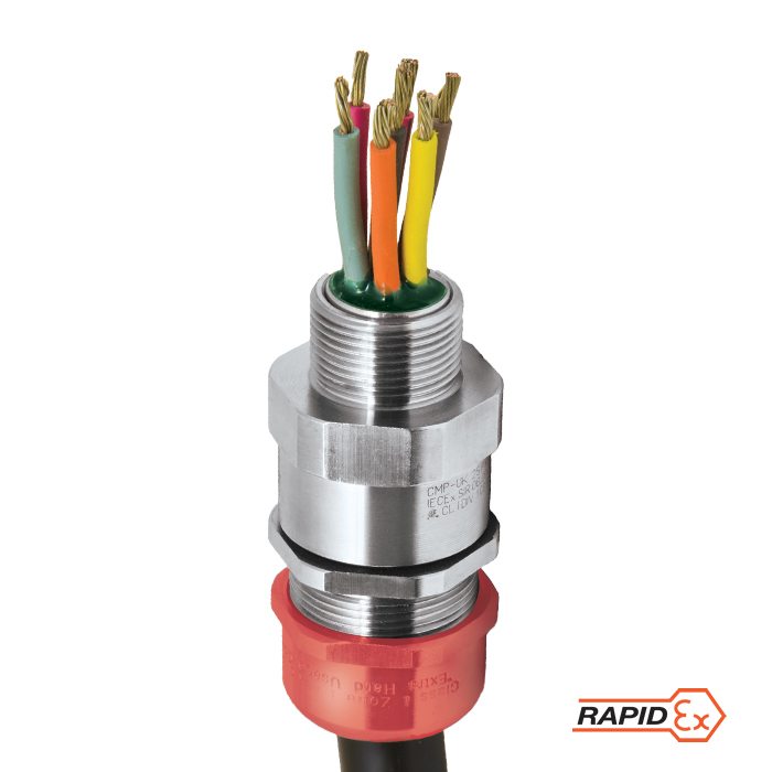
Globally Approved, Explosive Atmosphere RapidEx Barrier Cable Gland
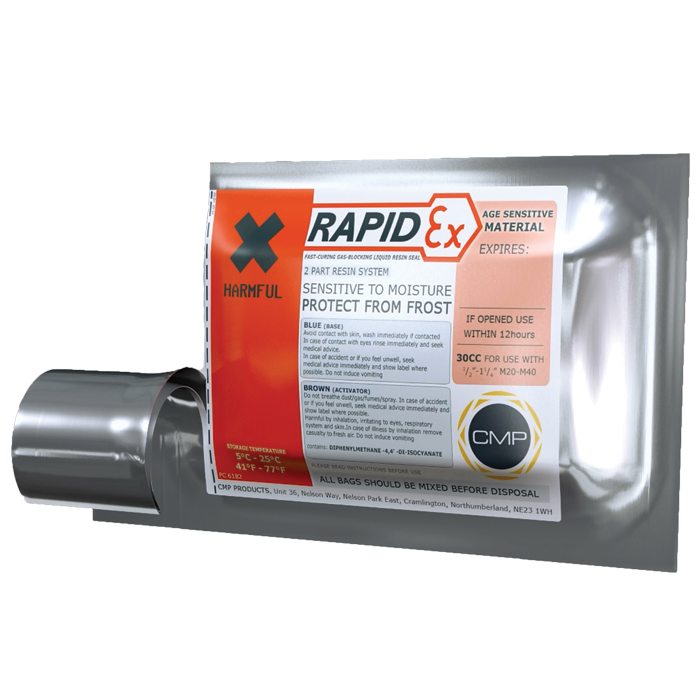
• RapidEx liquid pour sealing system
– Enhances reliability, reduces risk
– Reduces man hours
– Reduces cost
• Direct & remote installation
• Superior levels of cable retention
• Displacement type environmental seal
• Designed to prevent Coldflow
• Deluge protected
• -60°C to +85°C
• Globally marked, IECEx, ATEX & cCSAus
• Once any cable inner sheath/bedding has been removed, the RapidEx liquid resin barrier seals directly around the internal cable cores, completely eliminating any risk of coldflow on all cable types
PATENT GRANTED: ES 2287986, NO 2287986, TR 2287986, AU 2010284848, AU 2014274614, GB 2485114, SG 178839,
US 8872027, US 9484133, US 9774178, MY 153846, US 10193321, US1034078
| Design Specification | BS 6121:Part 1:1989, IEC 62444, EN 62444 |
| Mechanical Classifications* | Impact = Level 8, Retention = Class B |
| Enclosure Protection | IK10 to IEC 62262 (20 joules) Brass & Stainless Steel only |
| ATEX Certificate | CML 18ATEX1325X, CML 18ATEX4317X |
| UKEX Certificate | CML 21UKEX1214X, CML 21UKEX4215X |
| Code of Protection | II 2G, II 1D, Ex db IIC Gb, Ex eb IIC Gb, Ex ta IIIC Da II 3G Ex nR IIC Gc, IM2 Ex db I Mb, Ex eb I Mb |
| Compliance Standards | EN 60079-0,1,7,15,31 |
| IECEx Certificate | IECEx CML 18.0182X |
| Code of Protection | Ex db IIC Gb, Ex eb IIC Gb, Ex nR IIC Gc, Ex ta IIIC Da, Ex db I Mb, Ex eb I Mb |
| Compliance Standards | IEC 60079-0,1,7,15,31 |
| cCSAus Certificate (20s16 - 100) | 2288626 |
| CSAus Code of Protection*** | Class I, Div. 1, 2 Groups A, B, C and D; Class II, Div. 1, 2 Groups E, F and G; Class III, Div. 1, 2; Type 4X: Oil Resistant II: Class I, Zone 1 AEx d IIC Gb, AEx e IIC Gb, Class I, Zone 2 AEx nR IIC Gc, Class I, Zone 20 AEx ta IIIC Da |
| cCSA Code of Protection*** | Class I, Div. 1, 2 Groups A, B, C and D; Class II, Div. 1, 2 Groups E, F and G; Class III, Div. 1, 2; Type 4X: Oil Resistant II: Ex d IIC Gb, Ex e IIC Gb, Ex nR IIC Gc, Ex ta IIIC Da |
| Compliance Standards | CAN/CSA-C22.2 No 0,18,25,30,94,174, CAN/CSA-E60079-0,1,7,31 CAN/CSA-E61241-1-1, Part 1-1, ANSI/UL 514B Ed 5, ANSI/UL 50 Ed 11, ANSI/UL 2225 Ed 4, UL60079-0:07 |
| EAC Certificate | C-GB.A07.B.04595/22 |
| UkrSEPRO | CU 19.0371X |
| CCOE / PESO (India) Certificate | Ex d: P548696, Ex e: P533772 Ex nR: P548695 |
| CCC Certificate | 2020322313003190 |
| INMETRO Certificate | TÜV 12.2073X |
| KCs Certificate | Size 20S16 - 32 Size 40 - 63S Size 63 - 100 |
| RETIE Certificate | 03866 |
| Marine Approvals | LRS: 01/00172, DNV: TAE00000Y, ABS: 20-LD1948801-PDA, BV: 43180/A1BV |
| Ingress Protection Rating ** | IP66, IP67 & IP68 |
| Deluge Protection Compliance | DTS01 : 91 |
| Cable Gland Material | Electroless Nickel Plated Brass, Brass, Stainless Steel, Aluminium |
| Seal Material | CMP SOLO LSF Halogen Free Thermoset Elastomer / RapidEx Barrier Compound |
| Cable Type | Unarmoured (where permitted by code) |
| Sealing Technique | Unique CMP ‘LRS’ Outer Seal (Load Retention Seal) |
| Sealing Area(s) | RapidEx Resin Barrier & Cable Outer Sheath |
| Optional Accessories | Locknuts, Earth Tags, Serrated Washers, Entry Thread Seals, Shrouds,Ingress Discs |
| Optional Installation Tools | Spanners |
| ECAS Certificate | 24-03-106290/E24-03-110155/NB0007 |
| SANS | MS-XPL21962 21.0305X |
Note : * Mechanical & Electrical Classifications applied as per IEC 62444 & EN 62444
** When CMP installation accessories are used. Refer to Maintaining a Seal for further information.
***Where the cable is permitted by code (NEC and/or CEC)
**** IP68 tested to a minimum depth of 30 metres for 12 hours, alternate depths / durations can be provided upon request
Certificates


Product Selection Table
Click here to view how to order
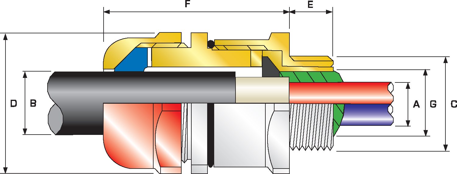
| Combined Ordering Reference (*Nickel Plated Brass NPT) | Available Entry Threads 'C' (Alternative Metric Thread Lengths Available) | Number of Cores | Diameter Over Conductors 'A' | Cable Bedding Diameter 'G' | Overall Cable Diameter 'B' | Across Flats 'D' | Across Corners 'D' | Protrusion Length 'F' | Shroud | Approx Weight Aluminum (oz) | ||||||
| Size | Type | Ordering Suffix | NPT | NPT (Option) | Metric (Option) | Thread Length (NPT) 'E' | Max | Max | Min | Max | Max | Max | ||||
| 20S16 | PXSS2KREX | 1EX531 | ½" | ¾" | M20 | 0.78 | 21 | 0.34 | 0.34 | 0.12 | 0.34 | 1.18 | 1.30 | 2.09 | PVC06 | 7.06 |
| 20S | PXSS2KREX | 1EX531 | ½" | ¾" | M20 | 0.78 | 21 | 0.46 | 0.46 | 0.24 | 0.46 | 1.18 | 1.30 | 2.09 | PVC06 | 7.06 |
| 20 | PXSS2KREX | 1EX531 | ½" | ¾" | M20 | 0.78 | 21 | 0.50 | 0.51 | 0.26 | 0.55 | 1.18 | 1.30 | 2.13 | PVC06 | 7.06 |
| 20L | PXSS2KREX | 1EX531 | ½" | ¾" | M20 | 0.78 | 21 | 0.50 | 0.51 | 0.41 | 0.63 | 1.18 | 1.30 | 2.13 | PVC06 | 7.06 |
| 25 | PXSS2KREX | 1EX532 | ¾" | 1" | M25 | 0.80 | 30 | 0.69 | 0.70 | 0.44 | 0.79 | 1.42 | 1.56 | 2.36 | PVC09 | 11.64 |
| 32 | PXSS2KREX | 1EX533 | 1" | 1 ¼" | M32 | 0.98 | 50 | 0.93 | 0.94 | 0.67 | 1.04 | 1.61 | 1.78 | 2.41 | PVC10 | 13.76 |
| 32L | PXSS2KREX | 1EX533 | 1" | 1 ¼" | M32 | 0.98 | 50 | 0.93 | 0.94 | 0.79 | 1.08 | 1.61 | 1.78 | 2.41 | PVC10 | 13.76 |
| 40 | PXSS2KREX | 1EX534 | 1 ¼" | 1 ½" | M40 | 1.01 | 59 | 1.18 | 1.19 | 0.87 | 1.26 | 1.97 | 2.17 | 2.46 | PVC13 | 19.75 |
| 50S | PXSS2KREX | 1EX535 | 1 ½" | 2" | M50 | 1.03 | 89 | 1.44 | 1.45 | 1.16 | 1.50 | 2.17 | 2.38 | 2.57 | PVC15 | 23.28 |
| 50 | PXSS2KREX | 1EX536 | 2" | 2 ½" | M50 | 1.06 | 115 | 1.61 | 1.63 | 1.40 | 1.73 | 2.76 | 3.03 | 2.66 | PVC21 | 25.75 |
| 63S | PXSS2KREX | 1EX536 | 2" | 2 ½" | M63 | 1.06 | 115 | 1.89 | 1.91 | 1.58 | 1.97 | 2.76 | 3.03 | 2.80 | PVC21 | 37.74 |
| 63 | PXSS2KREX | 1EX537 | 2 ½" | 3" | M63 | 1.57 | 115 | 2.11 | 2.13 | 1.86 | 2.20 | 3.15 | 3.47 | 2.77 | PVC25 | 37.39 |
| 75S | PXSS2KREX | 1EX537 | 2 ½" | 3" | M75 | 1.57 | 140 | 2.36 | 2.37 | 2.08 | 2.44 | 3.15 | 3.47 | 2.97 | PVC25 | 45.86 |
| 75 | PXSS2KREX | 1EX538 | 3" | 3 ½" | M75 | 1.63 | 140 | 2.53 | 2.53 | 2.33 | 2.67 | 3.94 | 4.33 | 2.95 | PVC30 | 45.86 |
| 90 | PXSS2KREX | 1EX539 | 3 ½" | 4" | M90 | 1.69 | 140 | 2.96 | 2.98 | 2.62 | 3.13 | 4.25 | 4.68 | 3.73 | PVC31 | 106.53 |
| 100 | PXSS2KREX | 1EX5310 | 3 ½" | 4" | M100 | 1.69 | 200 | 3.29 | 3.38 | 2.99 | 3.58 | 4.84 | 5.33 | 3.40 | LSF33 | 141.10 |
| *Note : For material options please change the suffix in the ordering reference ; Brass (no suffix required), Nickel Plated Brass “5” (as standard), 316 Grade Stainless Steel “4”, Copper Free Aluminum “1” For NPT options please change the following digits after the material suffix ; ½” = 31, ¾” = 32, 1” = 33, 1 ¼” = 34, 1 ½” = 35, 2” = 36, 2 ½” = 37, 3” = 38, 3 ½” = 39, 4” = 310 (Brass requires prefix “0”) |
||||||||||||||||
| Examples: 32PXSS2KREX1EX534 = Nickel Plated Brass 1 ¼” NPT, 25PXSS2KREX1EX432 = Stainless Steel ¾” NPT, 20PXSS2KREX1EX5 Nickel Plated Brass M20 | ||||||||||||||||
| Dimensions displayed in inches unless otherwise stated | ||||||||||||||||
| Cable Gland Size | Available Entry Threads 'C' (Alternate Metric Thread Lengths Available) | Number of Cores | Diameter Over Conductors 'A' | Cable Bedding Diameter 'G' | Overall Cable Diameter 'B' | Across Flats 'D' | Across Corners 'D' | Protrusion Length 'F' | Combined Ordering Reference (*Brass Metric) | Shroud | Cable Gland Weight (Kgs) |
|||||||
| Standard | Option | |||||||||||||||||
| Metric | Thread Length (Metric) 'E' | NPT | Thread Length (NPT) 'E' | NPT | Max | Min | Max | Max | Max | Size | Type | Ordering Suffix |
||||||
| 20S16 | M20 | 15.0 | ½" | 19.9 | ¾" | 21 | 8.6 | 8.6 | 3.1 | 8.6 | 30.0 | 33.0 | 53.1 | 20S16 | PXSS2KREX | 1RA | PVC06 | 0.20 |
| 20S | M20 | 15.0 | ½" | 19.9 | ¾" | 21 | 11.7 | 11.7 | 6.1 | 11.7 | 30.0 | 33.0 | 53.1 | 20S | PXSS2KREX | 1RA | PVC06 | 0.20 |
| 20 | M20 | 15.0 | ½" | 19.9 | ¾" | 21 | 12.6 | 12.9 | 6.5 | 14.0 | 30.0 | 33.0 | 54.2 | 20 | PXSS2KREX | 1RA | PVC06 | 0.20 |
| 20L | M20 | 15.0 | ½" | 19.9 | ¾" | 21 | 12.6 | 12.9 | 10.5 | 15.9 | 30.0 | 33.0 | 54.2 | 20L | PXSS2KREX | 1RA | PVC06 | 0.20 |
| 25 | M25 | 15.0 | ¾" | 20.2 | 1" | 30 | 17.5 | 17.9 | 11.1 | 20.0 | 36.0 | 39.6 | 60.0 | 25 | PXSS2KREX | 1RA | PVC09 | 0.33 |
| 32 | M32 | 15.0 | 1" | 25.0 | 1 ¼" | 50 | 23.6 | 23.9 | 17.0 | 26.3 | 41.0 | 45.1 | 61.1 | 32 | PXSS2KREX | 1RA | PVC10 | 0.59 |
| 32L | M32 | 15.0 | 1" | 25.0 | 1 ¼" | 50 | 23.6 | 23.9 | 20.0 | 27.4 | 41.0 | 45.1 | 61.1 | 32L | PXSS2KREX | 1RA | PVC10 | 0.59 |
| 40 | M40 | 15.0 | 1 ¼" | 25.6 | 1 ½" | 59 | 30.0 | 30.3 | 22.0 | 32.1 | 50.0 | 55.0 | 62.4 | 40 | PXSS2KREX | 1RA | PVC13 | 0.56 |
| 50S | M50 | 15.0 | 1 ½" | 26.1 | 2" | 89 | 36.6 | 36.9 | 29.5 | 38.2 | 55.0 | 60.5 | 65.2 | 50S | PXSS2KREX | 1RA | PVC15 | 0.66 |
| 50 | M50 | 15.0 | 2" | 26.9 | 2 ½" | 115 | 41.0 | 41.3 | 35.6 | 44.0 | 60.0 | 66.0 | 67.6 | 50 | PXSS2KREX | 1RA | PVC18 | 0.73 |
| 63S | M63 | 15.0 | 2" | 26.9 | 2 ½" | 115 | 47.9 | 48.4 | 40.1 | 49.9 | 70.0 | 77.0 | 71.1 | 63S | PXSS2KREX | 1RA | PVC21 | 1.07 |
| 63 | M63 | 15.0 | 2 ½" | 39.9 | 3" | 115 | 53.7 | 54.0 | 47.2 | 55.9 | 75.0 | 82.5 | 70.4 | 63 | PXSS2KREX | 1RA | PVC23 | 1.06 |
| 75S | M75 | 15.0 | 2 ½" | 39.9 | 3" | 140 | 59.9 | 60.2 | 52.8 | 61.9 | 80.0 | 88.0 | 75.3 | 75S | PXSS2KREX | 1RA | PVC25 | 1.30 |
| 75 | M75 | 15.0 | 3" | 41.5 | 3 ½" | 140 | 64.3 | 64.2 | 59.1 | 67.9 | 85.0 | 93.5 | 74.9 | 75 | PXSS2KREX | 1RA | PVC27 | 1.30 |
| 90 | M90 | 20.0 | 3 ½" | 42.8 | 4" | 140 | 75.3 | 75.6 | 66.6 | 79.4 | 108.0 | 118.8 | 94.8 | 90 | PXSS2KREX | 1RA | PVC31 | 3.02 |
| 100 | M100 | 20.0 | 3 ½" | 42.8 | 4" | 200 | 85.6 | 85.9 | 76.0 | 90.9 | 123.0 | 135.3 | 86.3 | 100 | PXSS2KREX | 1RA | LSF33 | 4.00 |
| Dimensions displayed in millimeters unless otherwise stated | ||||||||||||||||||
IEC 60079-1 – Flameproof Path Properties
A flameproof joint or flame path is defined by IEC 60079-1 as a “place where the corresponding surfaces of two parts of an enclosure, or the conjunction of enclosures, come together and which prevents the transmission of an internal explosion to the explosive gas atmosphere surrounding the enclosure”.
Read moreTypical cable gland selection
Follow CMP's flowchart for guidance on how to select a cable gland based on your application and cable type.
Read moreOverview of Different Flameproof Sealing Methods
Considering the requirements for Flameproof type ‘d’ (Ex d) enclosures and the need for cable glands to maintain the integrity of the protection method by containment, we can observe the different options available to achieve this. Recognition must first be given to the fact that cables must be robust enough to enable a sealing ring to be applied, and ensure safety of installations. See also Clause 9.3.1 of IEC 60079-14:2013.
Read moreCable Gland for Cables Entering Ex d & Ex n Equipment
The following page identifies and illustrates the minimum requirements for flameproof type ‘d’ (Ex d) and type of enclosure protection ‘n’ (Ex n) cable glands.
Read moreCompatibility of Equipment, Cable & Cable Gland
It is essential that the cable gland is compatible with the cable with which it is intended to be installed with, and the combination of both cable and cable gland is capable of maintaining the integrity of the connected equipment. The long term technical integrity of any plant or project relies heavily on the correct selection of cable and cable glands to suit the installation. Emphasis on the selection process requires careful thought and significant attention to a lot of variable factors that ought to be taken into account.
Read moreIECEx Certification
The IEC (International Electrotechnical Comission) develops international standards and operates conformity assessment schemes in the fields of electrotechnology. One such scheme, IECEx is a single global certification scheme, based on IEC and ISO international standards.
Read moreTypes of Sealing Rings
Some cables, that bear low smoke and fume, zero halogen or halogen free characteristics may have an inner bedding that is extruded from a compound which has not been fully cured during the manufacturing process. This is often referred to as a soft bedding, and brings an additional factor to consider when selecting appropriate cable glands.
Read moreMeeting the ATEX Directive
Applicable to the ATEX Directive 2014/34/EU are a number of conformity assessment procedures or modules and the circumstances when they must be used are determined by the nature of the equipment, product or protective system, and whether they are bespoke one-off solutions, or repeat items manufactured in batch production set up.
Read moreATEX & CE Marking
CE Marking i.e. Conformité Européenne, meaning European Conformity was introduced to enable the free movement of goods, products and equipment within the European Economic Area (EEA). When applying the CE mark to any item, the manufacturer is declaring that it complies with the requirements of all applicable European Directives. The CE mark should only be applied when the type of product falls within the scope of the Directive that is detailed in a corresponding EC Declaration of Conformity.
Read moreCMP Products Cable Gland Identification
Apart from the customary product, and certification (where it is required) marking, CMP Products also provides easy identification indicators to ensure that the correct cable gland is used in the correct environment.
Read moreCables Permitted in Hazardous Locations
In accordance with API 500 (14F), API 505 (14FZ), National Electrical Code (NEC) 2020 and C22.1-18 (Canadian Electric Code) any cable for use in a classified location must firstly be of a type permitted in the location, and secondly be tested and approved to standards specific to the application.
Read moreTypical Class I Zone 2 & Safe Area Sealing Methods
An illustrative example of Typical Class I Zone 2 & Safe Area Sealing Methods
Read moreVisit our Knowledge Base for technical expertise and advice, gathered over CMP's 60+ years' experience in the art of terminating cable glands.
View Profile